|
Building the Model Airways 1/16th Scale Sopwith Camel
Partial Kit 2 of 8
Finishing the Fuselage
OK. I can do this. Kit 2 is essentially all white metal parts along with some wire, thread,
a brass tube, and some copper tape. I've worked with white metal before so
unless I superglue my fingers together (again) this should be no problem.
The first step immediately puts the lie to the claim that the kit
comes with "all the tools you'll need". You have to cut the brass pipe into
three pieces and bevel it. Unless you want to saw through this thing with the
x-acto or the small file provided, your going to need something else. I used my dremel with
a cutting wheel and it worked just fine.
The first order of business is the engine mount. Glue
the pieces together and mount it to the frame using the provided eyelets. The
brass tubes are the carburator air intakes.
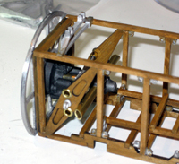
I decided to paint the mount with Testors gunmetal so there'd
be some contrast when everything else was installed.
The cockpit area is next. I gave the panel an extra coat of
varnish. The Instruments themselves are all white metal with printed paper dials
that must be cut out and glued to the instruments.
Interestingly, the kit does not provide a compass strip for the magnetic
compass, so I made one up in Photoshop printed it on my laser printer.

Next comes the fuel and oil tanks along with the throttle and
mixture controls. All of this gets wired together with the copper wire. The wire
is also use to connect the instruments to the engine (and later to the pitot).
The wire is supposed to represent both electical wires and plumbing. I might have preferred
that a different media be used, but it works fine as is.
The rudder bar and control yoke are hinged and will later be
cabled to the control surfaces. At the moment they just flop around freely.
The cockpit's wicker seat is a white metal part, so some Hull
Tallow paint (provided) is used along with a dark wash to get the right effect.
The copper tape is used to represent the straps on the main
fuel tank.
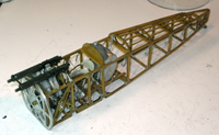
Last to go on are the machine guns, mounts, and ammunition
bays/shell ejector chutes, along with the tailskid with "bugee cord"
(represented by tan thread). I found the hinge pin on the tail skid too short to
reliably stay in the bearing, so I attached a short length of copper wire to it
that I then folded over the top of the eyelet to keep the skid in place. The
skid will later be connected to the rudder and pedals.
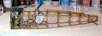
Finally, the turnbuckles and fuselage crossbracing are added
using grey thread to represent the wires. The cockpit coaming is added in kit 7
after the cabane struts are in place.
That's it for kit 2. Not too difficult if you have any
experience modeling with mixed media kits.
My research shows that the kit really does mimic the actual
contruction of the Camel to an amazing degree. As far as I can tell, the cockpit
is very accurate. It seems that every photo that I can find of a Camel cockpit is slightly different. The actual cockpit seems to vary somewhat depending
on which engine is installed, and a lot of the photos are of restorations or
recreations that have been modified to keep them flyable.
Clearly missing however, is any
wiring to the machinegun triggers or any any indication of how the
interrupter/synchronizer was implemented. Some of the kits white metal parts also suffer from a little
lack of detail for such a large scale. The machine guns in particular are a bit
disappointing. I had to drill out the barrels for instance. Also the kit's shell ejector chutes
are too short. I'll probably extend them later using either some of the extra
copper tape or perhaps just heavy paper. Sheet styrene would be the easiest but
it just seems wrong on this kit.
So far I've had great fun with this. Next up is the top wing.
We'll see if my patience holds out.
STEP 3 - The top wing
|