|
Building the Model Airways 1/16th Scale Sopwith Camel
Partial Kit 3 of 8
The Top Wing
Uh oh. Actual woodworking will be needed for this step.
Nothing too complicated so I should be okay. It'll be good practice for the last
kit where they evidently expect me to carve a propeller out of a block of wood.
I tried that once before many years ago for an old Guillows kit and result was
laughable. An Epic Fail as my kids would say now.
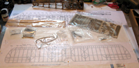
Here's what comes in kit 3. Lasercut ribs, some
basswood stock of various sizes, whitemetal fittings, a brass rod (for the
trailing edge), and the plans.
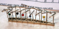
The first step for the top wing is to attach rib caps to all
of the ribs. This involves pinning the rib to the board using a small piece of
bassword to hold it 1/32" off of the board. After soaking the cap strips in
water for a few minutes so that they'll bend, you glue them to the rib edges and
use the T-pins to hold everthing in place while the glue dries. Repeat 32 times!
I have A.D.D., so I have to admit that this got real tedious for
me. I can't say I'm looking forward to the bottom wing.
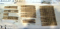
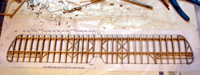
Here's the completed rib set. The two at the bottom center
are nearest the center. The pair on the left side with fewer holes are
doublethick and are near the cabane strut attachments. The stubs on the left
side are the edges of the airlerons.
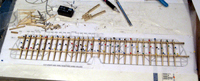
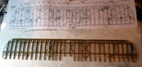
Once the ribs are done they need to be slid onto the spars
and pinned in place on the plan. When everything is aligned, thinned wood glue
is brushed onto the spars and allowed to dry.
When that is all dry, you add the various cross braces along
with the aileron spars and ribs. The spars must all be tapered to fit the
wingtip spar and then notched (the rat tail file very handy here) and tapered to fit the whitemetal wing tip.
Now comes that woodworking part. The leading edge must be
carved from a stip of bassword into something resembling the leading edge of an
airfoil. Fortunately, bassword is soft so an x-acto can be used for a very rough
shape that can then be sanded into a rounded form. I actually managed this
without too much trouble. When you have the right shape, the back side of the
tips must be notched to fit over the wing tips then rounded off and tapered to
blend.
The instructions suggest staining the wing now since would be
much harder after all the metal parts are in place.
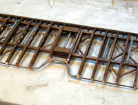
The spacer bars must all be drilled through at both ends for
the rigging lines before mounting them. I also discovered quickly that it is
MUCH easier to attach the turnbuckles and thread the rigging through the bar
before it is mounted. Four of the bars have mounting points for the struts and
these are attached to the bottom of the main spars, the others are attached to
the top. Then the cross brace rigging is added.
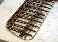
Now the center ribs are shaped to accept the trailing edge
cutout and the trailing edge rod is glued in place. Copper tape is used to blend
the edge to the ribs.
Note that the wing has been built with the ailerons as an
integral part. Time to get out your dremel and the cutting wheel.
 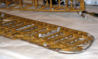
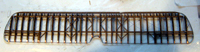
The ailerons are cut away from the wing assembly and
remounted with hinges. Then the control horn and wire guides are added. The
control wires will later be run to the yoke in the cockpit. The bottom view
shows the mounting points for the main struts.
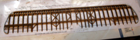
The last step is to add the framing around the visibility
cutout in the center of the wing. The center of the upper wing is not covered
with fabric in order to provide the pilot with a better view up and forward.
Well, once again I survived. Other than being bored by the
seemingly endless rib capping, it was fun. Even the leading edge wasn't too bad.
Fortunately, the Camel's top wing is flat so the spars can be straight. Not so
with the bottom wing which has considerable dihedral.
That challenge comes next.
STEP 4 - The bottom wing
|