|
Building the Model Airways 1/16th Scale Sopwith Camel
Partial Kit 7 of 8
Mounting the top wing
Part 7 of the kit provides all the parts needed to mount the
top wing and finish everything except the engine and prop.
Any plastic modeler that has ever built a biplane knows that
the trickiest part is always mounting the top wing and getting all the struts
aligned so that the wing is straight and level. I'm sure this is not going to be
any different with this kit.
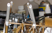
Step one is to drill holes in the cabane struts and glue the
rigging eyelets in place.
The next step is to attach the struts to the
fuselage. The trick here is getting them precisely positioned so that their
mounting holes will align with the mounting points on the top wing and the wing
will be straight and level and positioned properly with respect to the bottom
wing. If anything is off here, the wing struts won't fit later on.
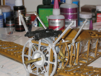
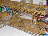
I made a brass wire jig to get the fore-aft spacing by simply
bending the wire to fit the mounting holes in the top wing. This would ensure
that the struts were the right distance apart. You can see it still in place on
the starboard pair of cabanes in the photo below
I used another wire cut to match the left/right distance
between the wing mounting points and used it to ensure the spacing was correct
in that direction.
In addition to the spacing you have to make sure that the
tops are all level. Getting them in the right spot on the fuselage is actually easy.
The front struts butt up right behind the firewall and the rear struts mount
directly over rib location C.
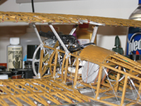
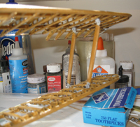
Before the top wing is mounted, you need to form and place
the cockpit coaming. This is just a black insulated copper wire that is bent into
shape and glued to the fuselage and the rear struts. Getting the shape right and
the same on both sides takes a little fiddling. I started in the rear and worked
forward eventually joining the wire ends in the middle at the front. As the
instructions point out, the final shape is a little like a potato chip.
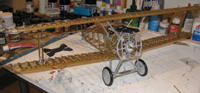
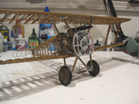
Now it's time to mount the top wing. If the struts are
positioned properly then it should drop easily in to place.
And it fits! Four faux bolts are used to attach the wing to
the struts and are then glued into place.
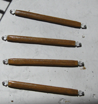
Next the wing struts need to be made. A strip of 1/4 x 3/32
bassword is cut into four lengths of 2 25/32". A slot is cut in each end (I used
my dremel cutting wheel) and the metal strut ends glued into the slots
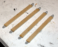
Next the wood needs to be tapered at the ends and rounded at
the front and back and of course stained to match the rest of the wood.
Now, if the top wing and bottom wing are properly aligned,
the struts should mount easily between the wings.
And they actually fit! I'm not sure what it says about my
modeling skills that I was so surprised that the struts went right on without
having to twist, stretch, bend, warp, or cut something. To quote Han Solo: "Ya
know, sometimes I amaze even myself"
With the wing safely in place. The wind driven fuel pump goes
in place on the right cabane and the pitot tube on the right wing strut. Copper
wire is used to represent the piping.
All that's left is the rigging. I ran the aileron control
cable first. I ignored the instructions here as they say to use one continuous
line from the yoke, through the wing structure and back to the yoke. That would
take someone with much smaller hands than I have (and more patience). I used
three lines. One each from either side of the yoke through each bottom wing in
front of the spar through the pulley to the control horn and bottom aileron. The
third through the top wing and pulleys on either side to each control horn and
aileron then down to meet the lines on the bottom wing. I used clamps to hold
each aileron in the neutral position and braced the yoke in the center while the
lines were run and attached.
After that, the turnbuckles for the static rigging are
attached and then the rest of the rigging.
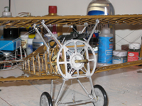 
I decided after looking at this thing sitting on my workbench
for several days, that I really hated the bare metal cabane and landing gear
struts. Obviously the kit uses metal for strength, but they're wood on the real
plane. So I gave them a base coat of light wood paint and then used the same
English Oak stain that went on the rest of the model.
Once the struts were painted, the metal wheels and axle cover
(which would be fabric covered on the real plane) became glaring sore spots. I
initially painted these green, which is what 90%+ of the references say they
should be. However, having the wheels be the only green on an otherwise, brown,
metal, and brass creation made them stand out like ugly warts so I repainted
them brown. Fortunately, there's small minority of people who swear that the
paint used by the RAF in WWI was actually brown and not green so I'm using that
as justification. Actually the green was just ugly.
There actually wasn't anything in this step that I haven't
done before with plastic kits. In fact I think I had less trouble mounting this
wing than I ever had with any of the plastic biplane kits I've built.
So now its on to the finale. The engine and the dreaded
propeller.
STEP 8 - The engine and propeller
|