|
Building the Model Airways 1/16th Scale Sopwith Camel
Partial Kit 5 of 8
The Empennage
Well, I've made it to kit 5 of the 8 and it would seem to
represent the start of the downhill part of the race. Not only are we now past
halfway, but it looks like the hardest parts of the kit (other than that
propeller) are already done.
After slogging through the bottom wing last month, the tail
section was a breeze.
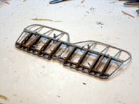
As with the wings, the tail starts with capping the ribs for
the stabilizer.
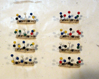
Fortunately for my sanity, there are only eight and they're
much smaller than the wing ribs.
While the glue on the ribs was drying, I assembled the fin
and rudder.
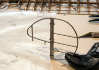
The assembly is all metal. The fin and rudder are joined by
crimping whitemetal hinges around them at the hinge points. Then the control
horn is glued to the rudder.
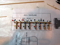
There is only a single spar on the stabilizer and only eight
ribs, so assembly is quick.
There is also no leading edge to carve. The whole rib and
spar assembly is mounted inside the stabilizer frame. The center part of the
spar need to be trimmed down to fit properly inside the frame.
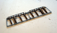
Unlike the wings, the compression bars used for the cross
rigging are wood pieces instead of metal, but otherwise the rigging process is
similar. The wood then gets its Englisk Oak stain and varnish.
The elevator is attached with clamps the same as the rudder
and the control horns are glued in place.
The rudder assembly is then attached to the stabilizer and
the whole thing is then glued in place on the fuselage.
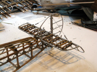
Since there are no locating pins or any of the other aids in
a plastic kit, the aligment must be carefully checked. The fin must be vertical
and centered and parallel to the fuselage center line. The stabilizer must be
level and perpendicular to the center line.
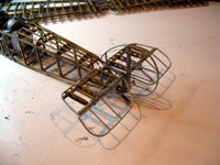
The bracing rigging is then added. The control wires for the
rudder and elevator are added next.
One long piece is used for the rudder. The "wire" is threaded
through the hole at the back of the rudder with half on each side. Then on each
side, it goes through the control horn, into the fuselage and under the seat to the
rudder bar, then back under the seat and finally connects to the tailskid. Make sure that the rudderbar is centered along with the rudder and
tailskid when tying off the lines.
I departed from the instructions while doing the elevator
rigging. The instuctions say to start and end the run on the control stick, but
it's way too tight in there to make that practical. I started by attaching the
center of the cable to the stick and then running the free ends from there.
On each side, one cable runs from the front of the stick
around a guide on the rudderbar, back under the seat, through the fuselage over
the top of the stabilizer to the horn and is terminated at the back of the
elevator. The other half runs from the back of the stick, under the seat to the
bottom control horn and the back of the elevator. Again care must be taken to
have the elevator and stick centered while all the wires are tightened and glued
in place.
Rigging the controls can be frustrating as there is little
room to work in the cockpit area and it all has to be done with tweasers. It's
very easy to get a cable wrapped around another one or around some other piece
of the fuselage while at the same time trying to keep everything taut and
centered. I thought I had it done a couple of times only to realize a cable was
tangled somewhere and had to be rerouted.
The end result however, is worth the struggle as moving the
cockpit controls will move the control surfaces appropriately (or vice-versa).
The only things left are to build the landing gear,
mount the wings, and build the engine - and the prop.
STEP 6 - The landing gear
|